The fabrication of the CST® framework is easily incorporated in to existing laboratory protocols. No CAD/CAM scanners or software are required either, making the entire process accessible to anyone with a light curing oven and/or handheld unit. The entire process takes approximately 30 minutes once the technician becomes familiar with the process.
Inspired by proven engineering principals applied in the construction of cable stayed bridges and in processes established for concrete reinforcement, the CST® technique incorporates several key elements that ensure the framework is resistant and durable:
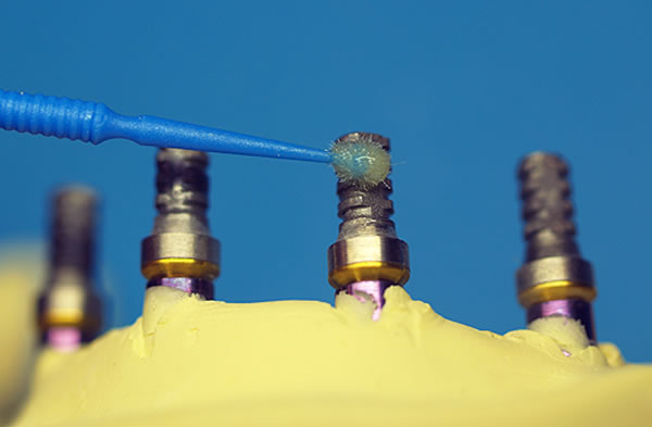
1. Preparation of Titanium Cylinders
In order to ensure an effective bond of the CST® fibers to the titanium cylinders, the cylinders are sandblasted with aluminum oxide or Rokatec, silanated and treated with a bonding agent.
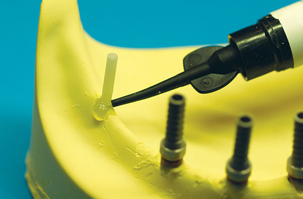
2. Temporary Support Pillars
The CST® temporary support pillars provide two functions. They act as a purchase point from which the CST® fibers are woven into the desired configuration while maintaining tension on the fibers. They also allow for the demarcation and creation of the support structures for the distal extensions.
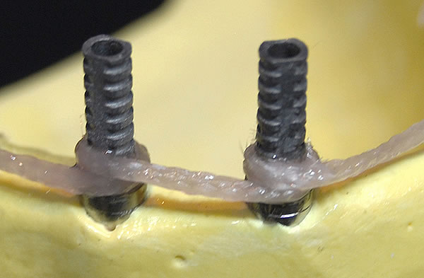
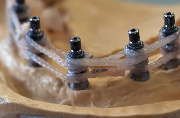
3. Wrapping Cylinders
In combination with proper surface preparation of titanium cylinders, wrapping the CST® fibers 360 degrees around the cylinders assures that the fibers adhere to the cylinder surface and keeps the complete CST® framework from slipping around the fixed cylinder positions when exposed to stress forces.
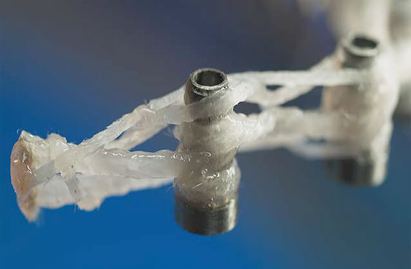
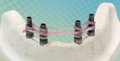
4. Primary Cable Structure
The foundation of the CST® framework is the creation of a three dimensional fiber base cable structure using the 1:6 hybrid compressible fibers. Three cable “runs” are made resulting in a solid fiber base around which acrylic will be processed. This base fiber structure is resistant to the compressive forces delivered to the framework intra-orally.
5. Distal Extension
As the CST® fibers are wrapped around the temporary support pillars a fiber structure is created that will reinforce the acrylic in the area of the distal extension. The third cable run is made at a 45 degree angle, and by applying known engineering principles, maximizes the resistance to stress forces in that area. The maximum recommended length of distal extension in a CST® case is 11mm.
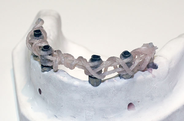
6. Cable Stays
The 1:4 hybrid compressible fiber is applied in two “back and forth” runs and wrapped around the base structure. This provides additional reinforcement and resistance to eccentric or chewing forces.
7. Passivity of Fit
Passivity of fit is essential in implant cases and the CST® technique results in fiber frameworks that are completely passive.
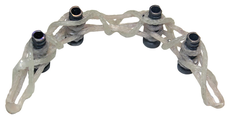
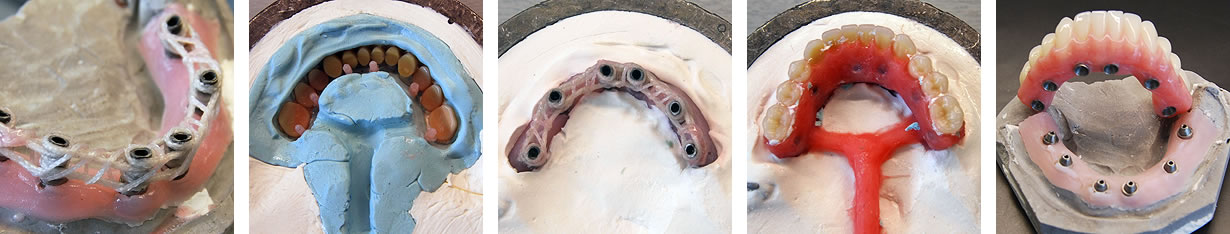
8. Finished Framework
Once light cured the finished CST® framework is now ready to be processed with acrylic using the preferred processing method and following usual protocols.
Please review the complete written instructions for detailed fabrication procedures for the CST® fiber implant framework

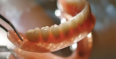 Resin-impregnated fiber reinforcement
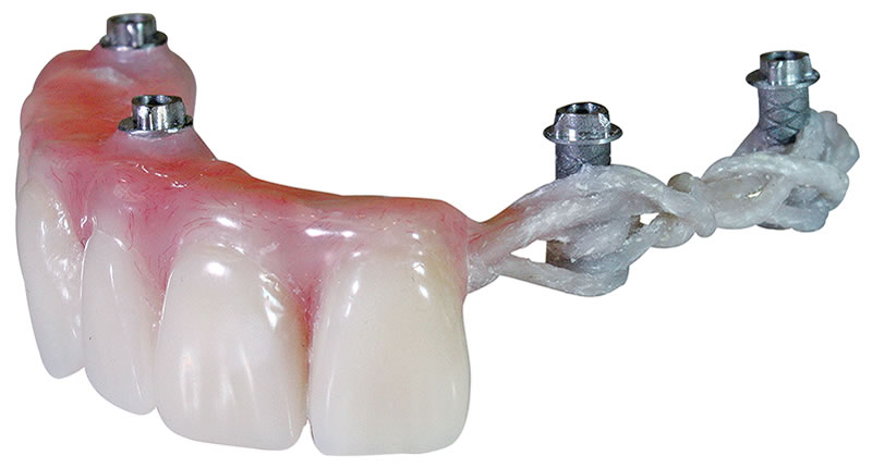
 Long-term fiber implant framework system
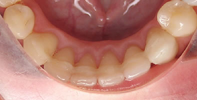 Dental glass splinting system
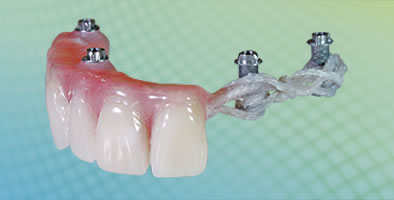
 Temporary fiber implant framework system